


-
 Courier delivery
-
 DHL Courier delivery
-
 Warranty 1 year
-
 Free 30-Day returns

 Overview
| Weight | 0.67 lbs |
|---|---|
| Dimensions | 150 × 150 × 50 in |
| Color |
Green |
 Processor
| Weight | 0.67 lbs |
|---|---|
| Dimensions | 150 × 150 × 50 in |
| Color |
Green |
 Display
| Weight | 0.67 lbs |
|---|---|
| Dimensions | 150 × 150 × 50 in |
| Color |
Green |
 RAM
RAM
| Weight | 0.67 lbs |
|---|---|
| Dimensions | 150 × 150 × 50 in |
| Color |
Green |
 Storage
| Weight | 0.67 lbs |
|---|---|
| Dimensions | 150 × 150 × 50 in |
| Color |
Green |
 Video Card
| Weight | 0.67 lbs |
|---|---|
| Dimensions | 150 × 150 × 50 in |
| Color |
Green |
 Connectivity
| Weight | 0.67 lbs |
|---|---|
| Dimensions | 150 × 150 × 50 in |
| Color |
Green |
 Features
| Weight | 0.67 lbs |
|---|---|
| Dimensions | 150 × 150 × 50 in |
| Color |
Green |
 Battery
| Weight | 0.67 lbs |
|---|---|
| Dimensions | 150 × 150 × 50 in |
| Color |
Green |
 General
| Weight | 0.67 lbs |
|---|---|
| Dimensions | 150 × 150 × 50 in |
| Color |
Green |
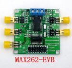
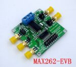
Features:
1. with a filter design software, with a microprocessor interface;
2. can control 64 different center frequency f0, 128 different quality factor Q and 4 kinds of work patterns;
3. the center frequency f0 and quality factor Q can be independently programmed;
4. can provide three clock input (external clock input, RC oscillator and crystal devices);
5. the central frequency f0 range of 1Hz ~ 140kHz, the maximum input clock 4MHz;
6. the filter circuit structure is simple, less external components, small size;
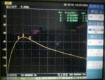
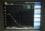
7. can achieve low-pass, high-pass, band-pass, band-stop and all-pass filter;
8. can be A, B single-stage input and output, but also AB cascade of two levels of input and output;
9. Product size: 50*50MM
10. Product weight: 22 grams
The main chip pin description:
V + – positive power input.
V- -Negative power input.
GND – Analog ground.
CLKA – external crystal oscillator and filter A part of the clock input, within the filter, the clock frequency is divided by 2.
CLKB – the clock input to filter B, also within the filter, the clock frequency is divided by 2.
CLKOUT – Clock output for crystal oscillator and R-C oscillation.
OSCOUT – Connects to a crystal or R-C oscillator for self-synchronization.
INA, INB – The signal input of the filter.
BPA, BPB – band-pass filter output.
LPA, LPB – low-pass filter output.
HPA, HPB – high-pass, with resistance, all-pass filter output.
WR – Writing to the active input. When connected to V +, the data can be entered into a programmable memory through the logical interface to complete the filter mode, f0 and Q settings. In addition, it can receive TTL level signals, and the rising edge latch input data.
A0, A1, A2, A3 – address input, can be used to complete the filter mode, f0 and Q of the corresponding settings.
D0, D1 – Data input, can be used to set the corresponding bits f0 and Q.
OP OUT – The amplifier output of the MAX262.
OP IN – The inverting input of the MAX262 amplifier.
Packing list:
Program-controlled filter * 1


You may also like


0.15mm Full Coverage Tempered Glass Film For IP 12 Mini 5.4inch
Price range: $36.76 through $38.92 Compare
0.23mm Unbroken Edge Full Screen Curved Privacy Tempered Film For IP XR 11 6.1 Inch
Price range: $32.54 through $33.65 Compare
0.3mm Full Glass Privacy Tempered Film For IP 5.4 Inch Two Pieces
Price range: $34.86 through $35.97 Compare
0.3mm Full Screen Curved Anti-Blue Light Tempered Film For IP 5.4 Inch Two Pieces Black
Price range: $36.40 through $40.79 Compare


Reviews
Clear filtersThere are no reviews yet.